
What steps do I need to take if I am adding solar panels after my Base system installation?
For the Base member:
Notify Base as soon as you decide to get solar.
This allows us to ensure your solar is installed in a way that's compatible with Base and that everything goes smoothly. Be sure to let us know who your solar installer is, and send us their contact information. After your solar panels are installed, Base will come install current transformers (CTs) to measure your solar production. This is essential for accurate billing and to ensure you receive solar buyback credits. CT installation can occur on the same day as your solar installation or afterwards.Send Base's solar requirements to your solar installer.
Your solar installer must configure your solar in a particular way and avoid disturbing any Base equipment during the installation. Share the information below with them to ensure the solar setup is compatible with your Base battery system and does not damage the Base equipment. You can direct them here: https://basepowercompany.com/solar-installers.
For the solar installer:
Do not remove or modify the Base battery system. Base systems are installed to provide home backup and intelligent grid services. Under no circumstances should any Base equipment—including the battery, inverter, or Hub/Disco, be disconnected or reconfigured during your install.
No back-fed equipment should be installed upstream of the Base SYN (25kWh or 50 kWH system) or Disco (Base Core)
Use a back-fed breaker. Your solar array must be connected via a back-fed breaker. Base does not support DC-coupled systems wired into the Base inverter. Your solar system must be AC-coupled with a dedicated solar inverter. No communication or wiring is necessary between the Base system and solar inverter. Do not line side tap solar leads into the Hub or Disco. If you are unsure whether your system will meet these requirements, please email us a wiring diagram to support@basepowercompany.com and we can confirm.
Coordinate Interconnection Agreement filing.
Do not submit a new Interconnection Agreement (IA) without first contacting Base at support@basepowercompany.com. The new solar IA must include the Base equipment. Duplicate filings can delay PTO approvals.
Email Base at support@basepowercompany.com with all solar installation information, including the package you plan to submit to the utility.
When ready, include Base's equipment specs in your IA documentation. Use the pair that matches the home's system:
Gen 1 (Hub) systems:
APX HV Battery US, Growatt APX HV, modular 5-30 kWh
Inverter (MIN 8200-11400TL-XH-US), Growatt MIN 8200-11400TL-XH-US
Base Core (Disco) systems: Reach out to Base at support@basepowercompany.com for the battery and inverter specifications needed for your IA documentation.
Coordinate installation schedule. Base needs to be prepared for data interruption during your solar installation. We receive emergency alerts anytime home power is shut off. To avoid falsely alerting the Base team of a possible emergency, please communicate the date and time your team will be on-site in advance so we know the reason for the shutoff.
Leave room for current transformers (CTs). After your solar array is installed, Base will return to add CTs for production monitoring and buyback credits.
Safely turn home power off and on for your solar installation. Shutting off the main breaker in the transfer switch is not sufficient, as this will cause the battery system to kick in and back up the home. The exact steps differ depending on whether the home has a Gen 1 Hub system or a Base Core Disco system, so select your system at the bottom of this article for the matching steps, then use them to safely power the system off before starting your work and back on when you're done
Reminder for sales & electrical teams:
Battery backup activates automatically during outages.
No additional load management is needed for solar.
AC-coupled solar will function normally alongside the Base inverter, which manages battery operations separately.
Base wiring diagram:
If you have a 25 kWh or 50 kWh system, scroll further down
If you have a 40 kWH Base Core System (Disco) :
Base Core three-line diagram, single install with solar, back-fed configuration.
For non-standard setups
This diagram covers a standard single-Disco, single-Energy Hub install with solar back-fed on the load side. For anything outside that, such as dual installs, non-standard panel configurations, or a setup that doesn't match this diagram, please reach out to Base at support@basepowercompany.com for further wiring diagrams.
How to safely cut home power at the Disco
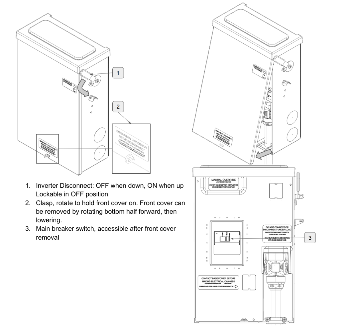
Because of how the Disco is wired into the home, its main breaker now acts as the home's main service disconnect. Switching it off cuts power to the whole home, not just to the Base battery system, so the VLLD must be switched off first.
1
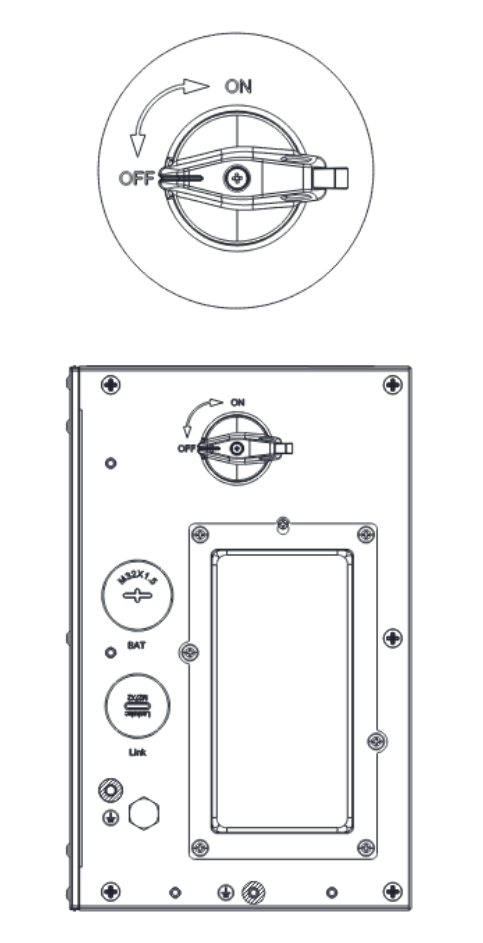
2Switch the VLLD, also called the knife switch (labeled 1 in the diagram above), to OFF. Down means off.
Open the Disco's front cover, rotating the bottom half forward and then lowering it off.
With the front cover off, switch the main breaker off (labeled 3 in the diagram above).
Confirm voltage is within safe range with a multimeter before proceeding.
How to safely restore home power at the Disco1Switch the main breaker back on (labeled 3 in the diagram above).
2Reinstall the Disco's front cover.
3Switch the VLLD, also called the knife switch (labeled 1 in the diagram above), back to ON. Up means on.
If you have a 25 kWh or 50 kWh System (Hub) :
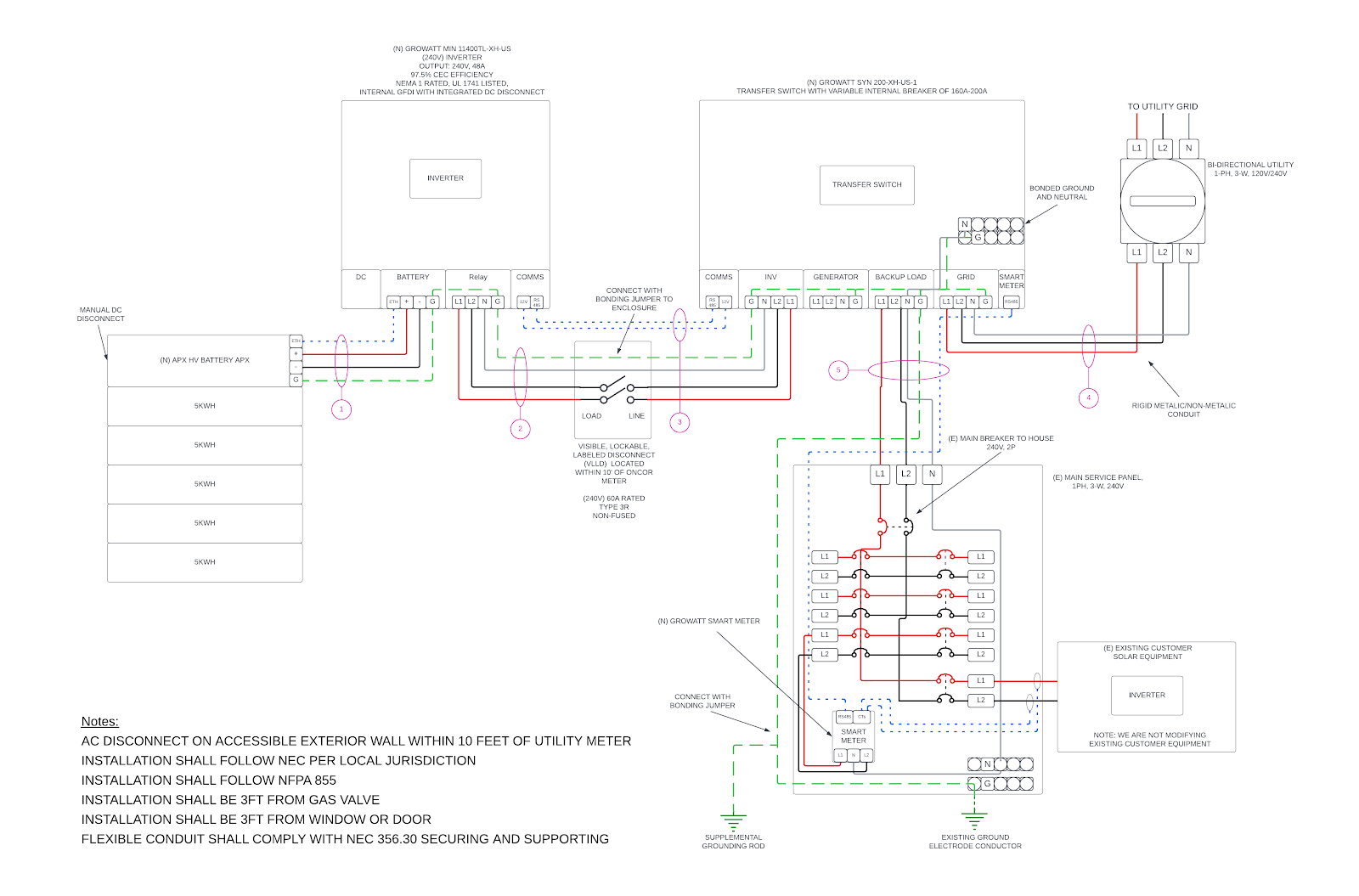
Here is a wiring diagram for a single 25 kWh ground-mounted Base battery. Actual configurations may vary.
How to safely power OFF the battery system before cutting home power:
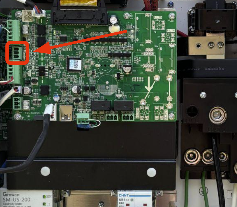
Locate the 3 pin jumper, inside a plastic bag on the inside of the Hub door.
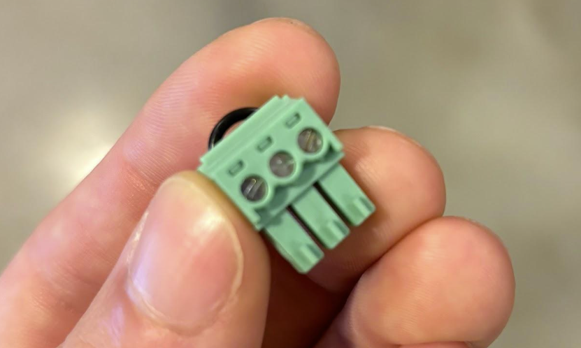
The Hub is the the white panel that contains our 200A service disconnect. Insert the bypass jumper into the Hub board.
This will ensure the customer home has power during service and there is no interference with home load.
Once the bypass jumper has been inserted, turn off the red battery switch located on the left side of the power module. The power module is the uppermost module on each battery stack.
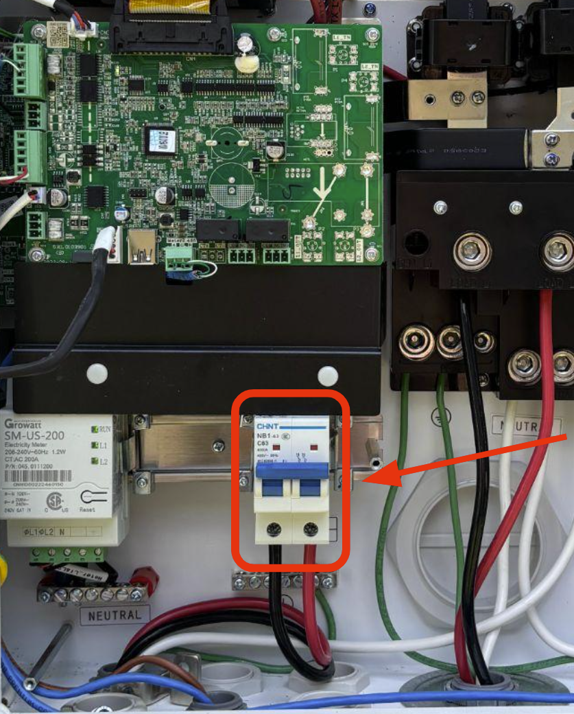
Flip off the 63A mini-breaker(s) in the Hub. Down = off/open.
Do not switch off the VLLD. Switching off the 63A breaker will de-energize the system. The VLLD mechanism can cause issues when switching on and off.
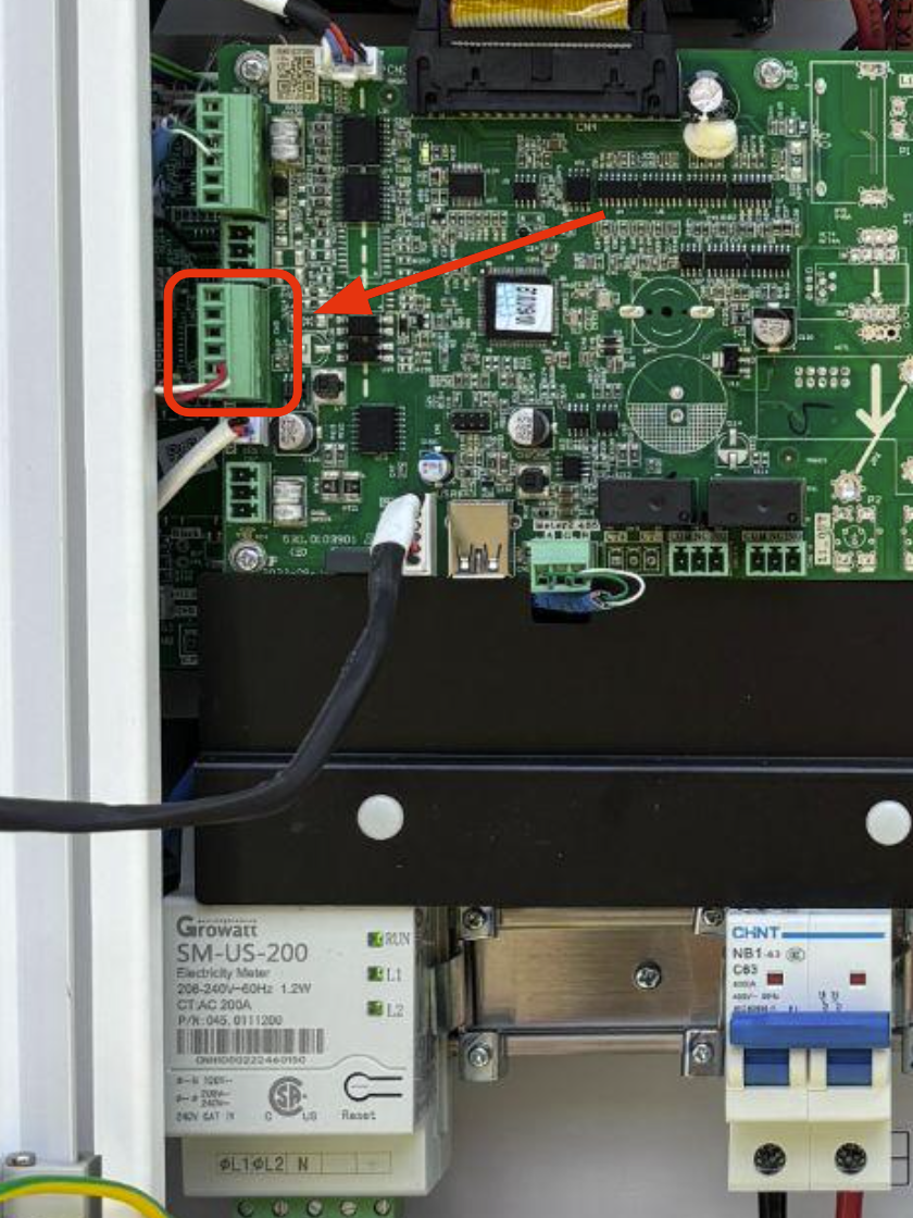
Remove the 12V power supply 6-pin jumper from the Hub. Ensure the Inverter lights turn off. The Inverter exists electrically between the battery and the Hub.
Wait 1 minute for residual charge in the battery to dissipate.
Confirm voltage is within safe range with a multimeter before proceeding.
How to safely power ON the battery system when you're done:
Insert the 12V power supply 6-pin jumper into the Hub. Ensure the Inverter lights turn on. The Inverter exists electrically between the battery and the Hub.
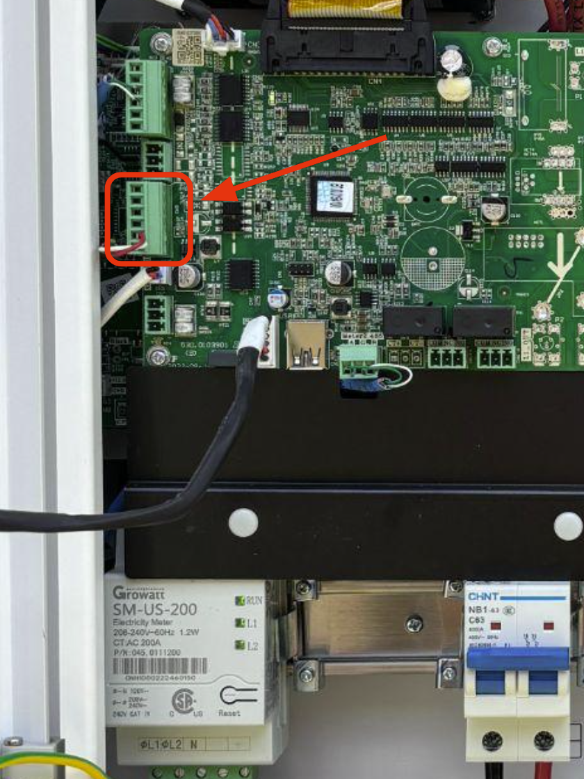
Ensure VLLD is in the ON position. Flip on the 63A mini-breaker(s) in the Hub. Up = on/closed.
Do not switch on the VLLD or 63A while the system is on-grid and battery is on. This will result in competing currents that have historically caused damage to the inverter.
Turn on the red battery switch located on the left side of the power module. The power module is the uppermost module on each battery stack.
Hold the start button on the right side of the power module for ~15 seconds. Ensure the power module screen illuminates, showing the state of charge of the battery.
Remove the bypass jumper from the Hub board. Replace the 3 pin jumper inside the plastic bag on the inside of the Hub door (or set it just inside the door).